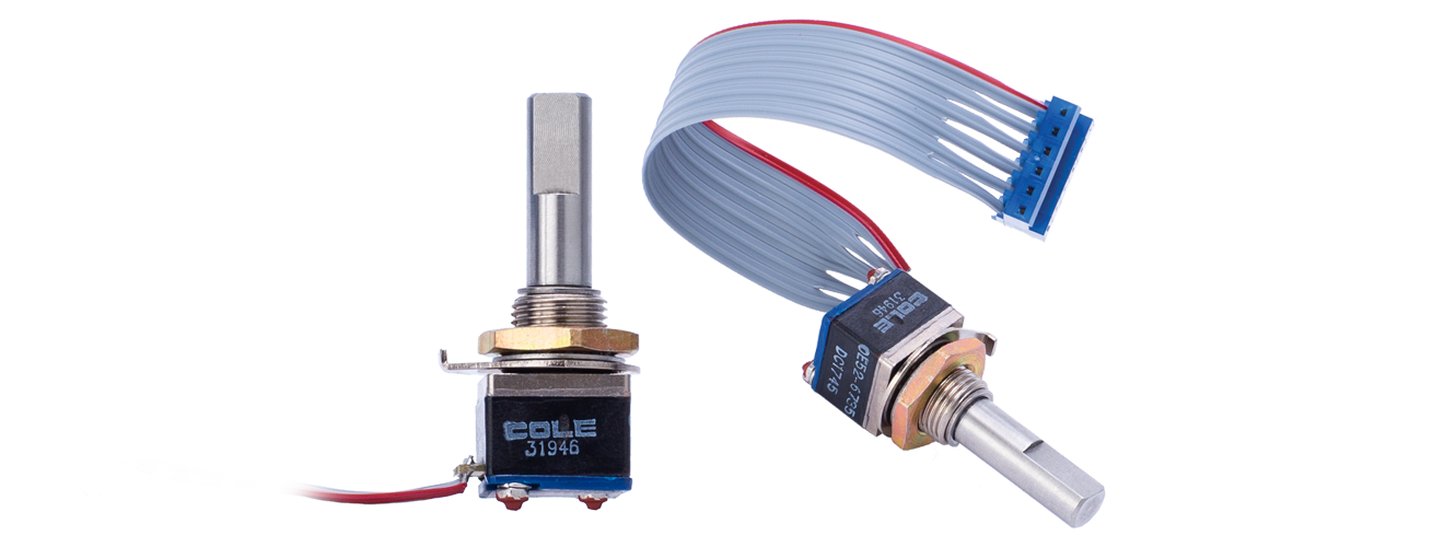
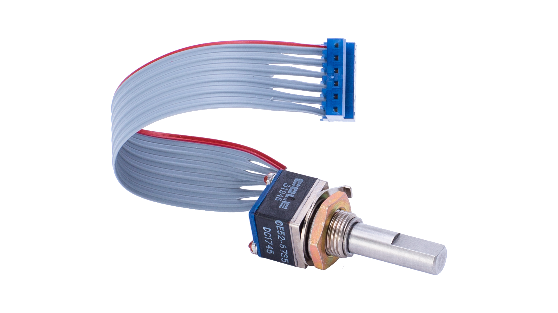
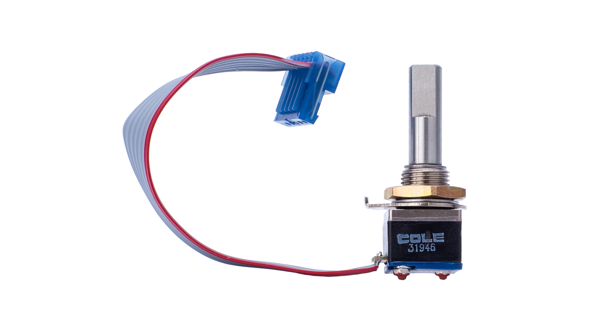
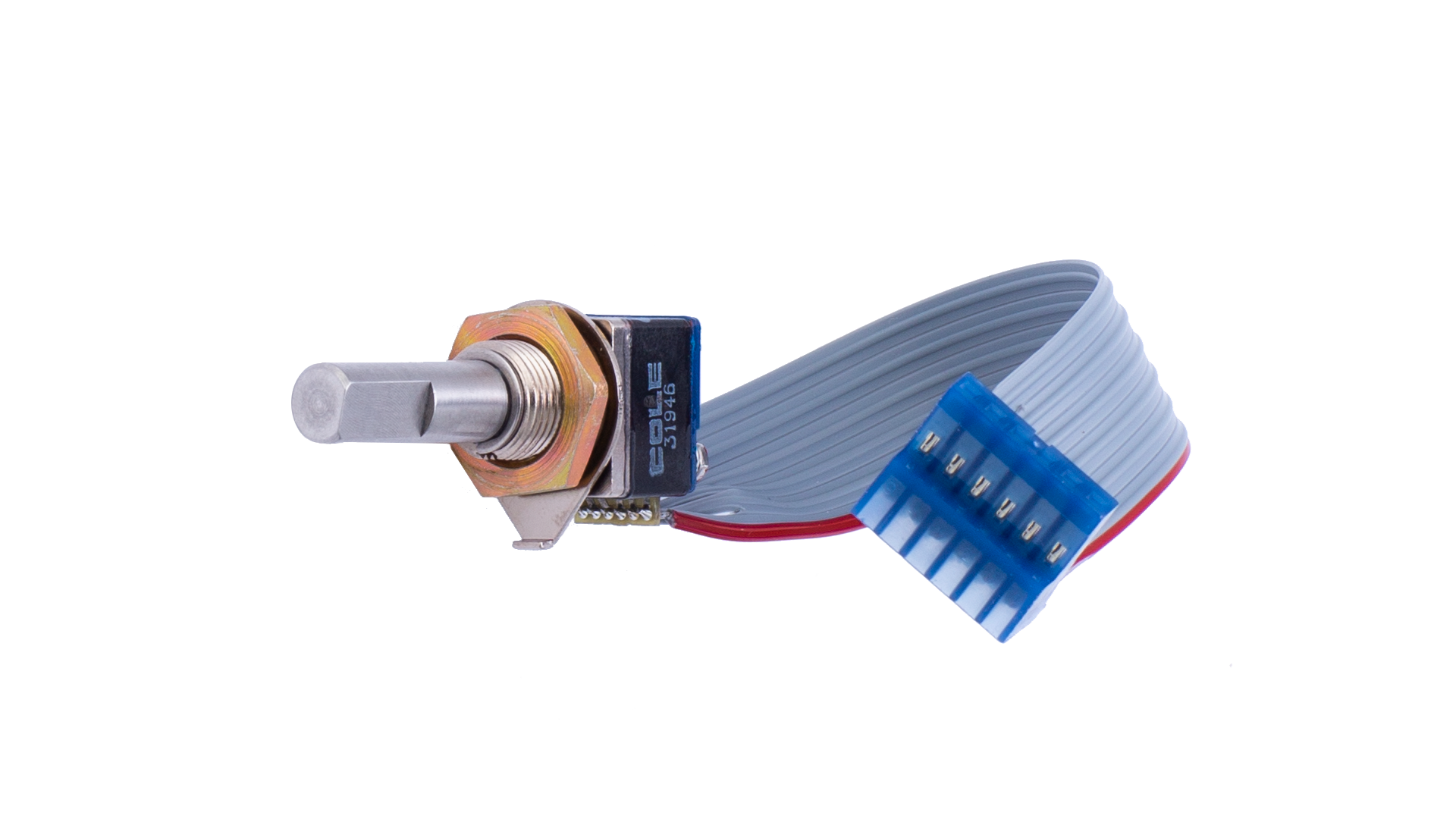
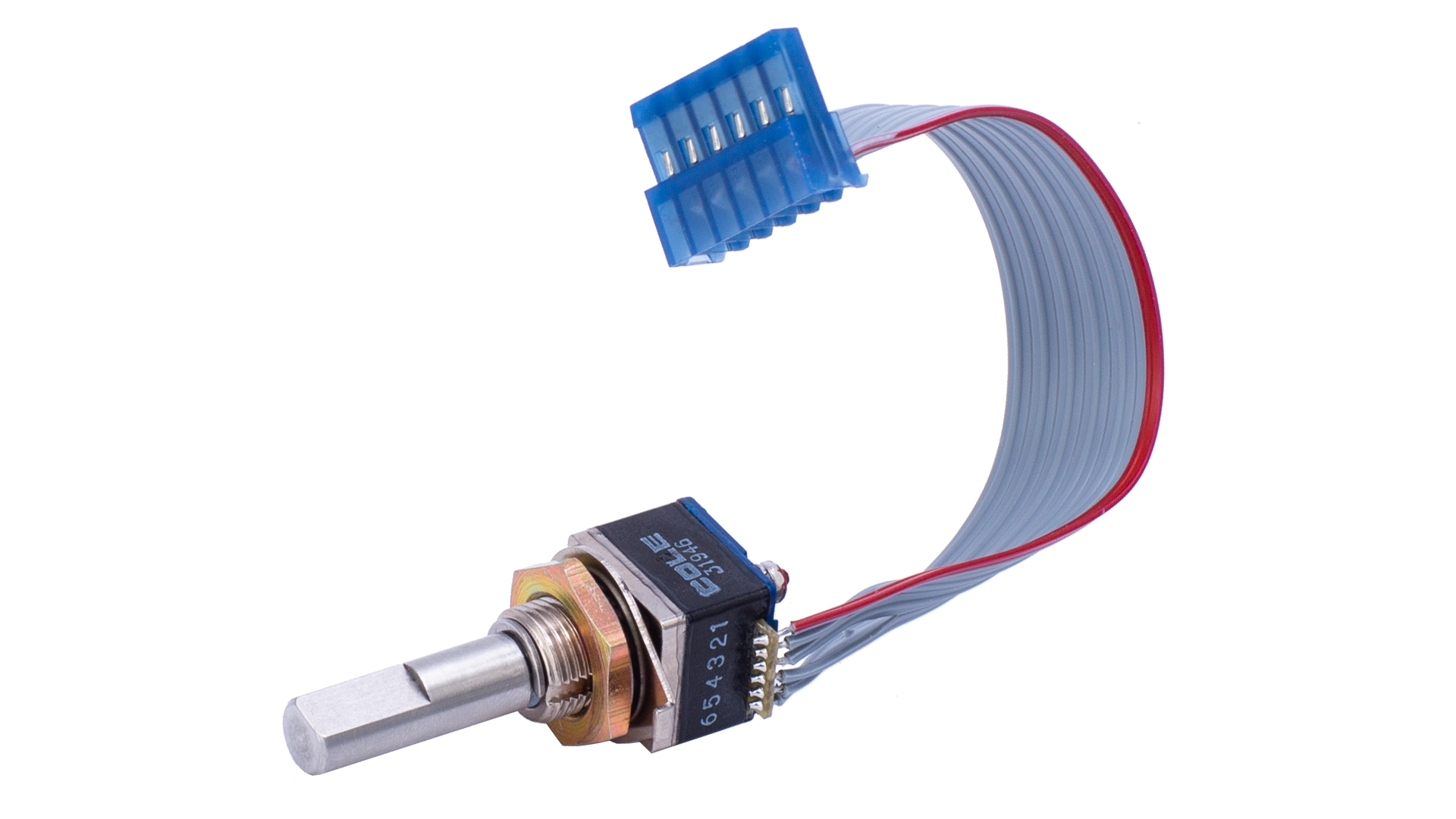
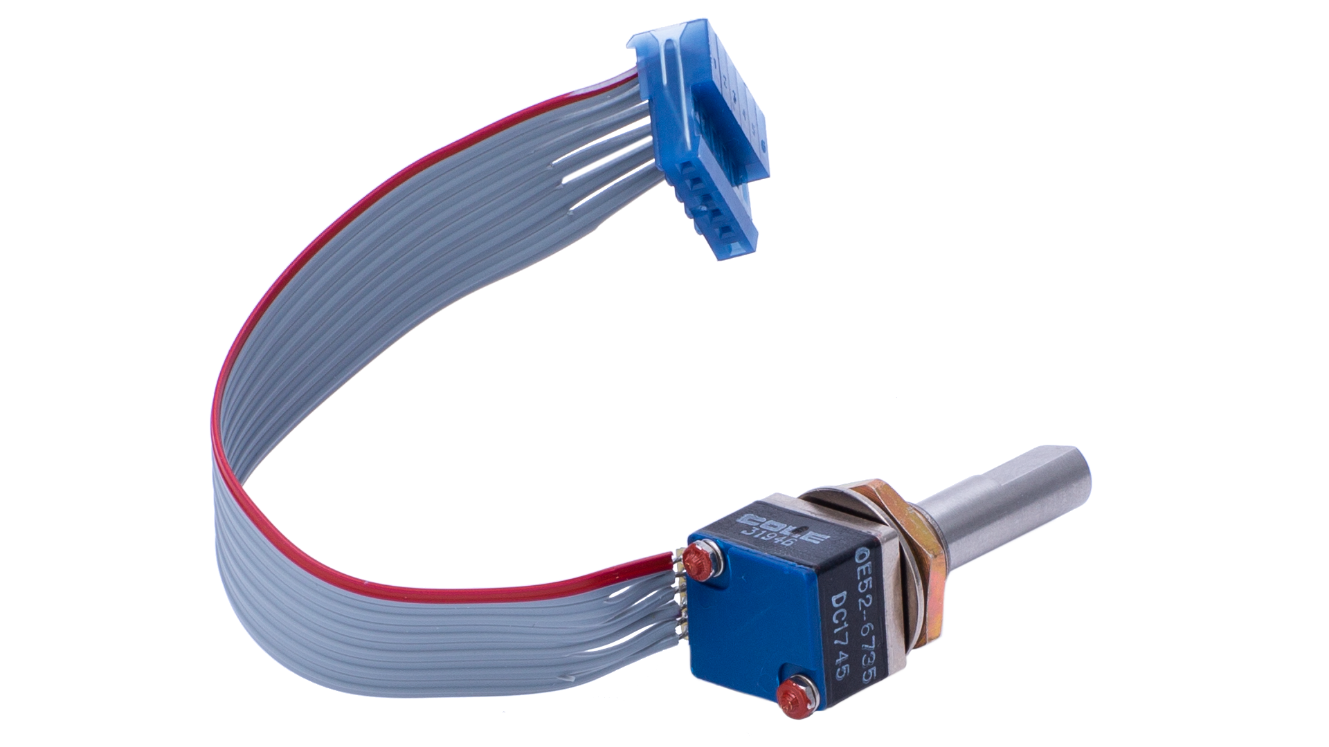
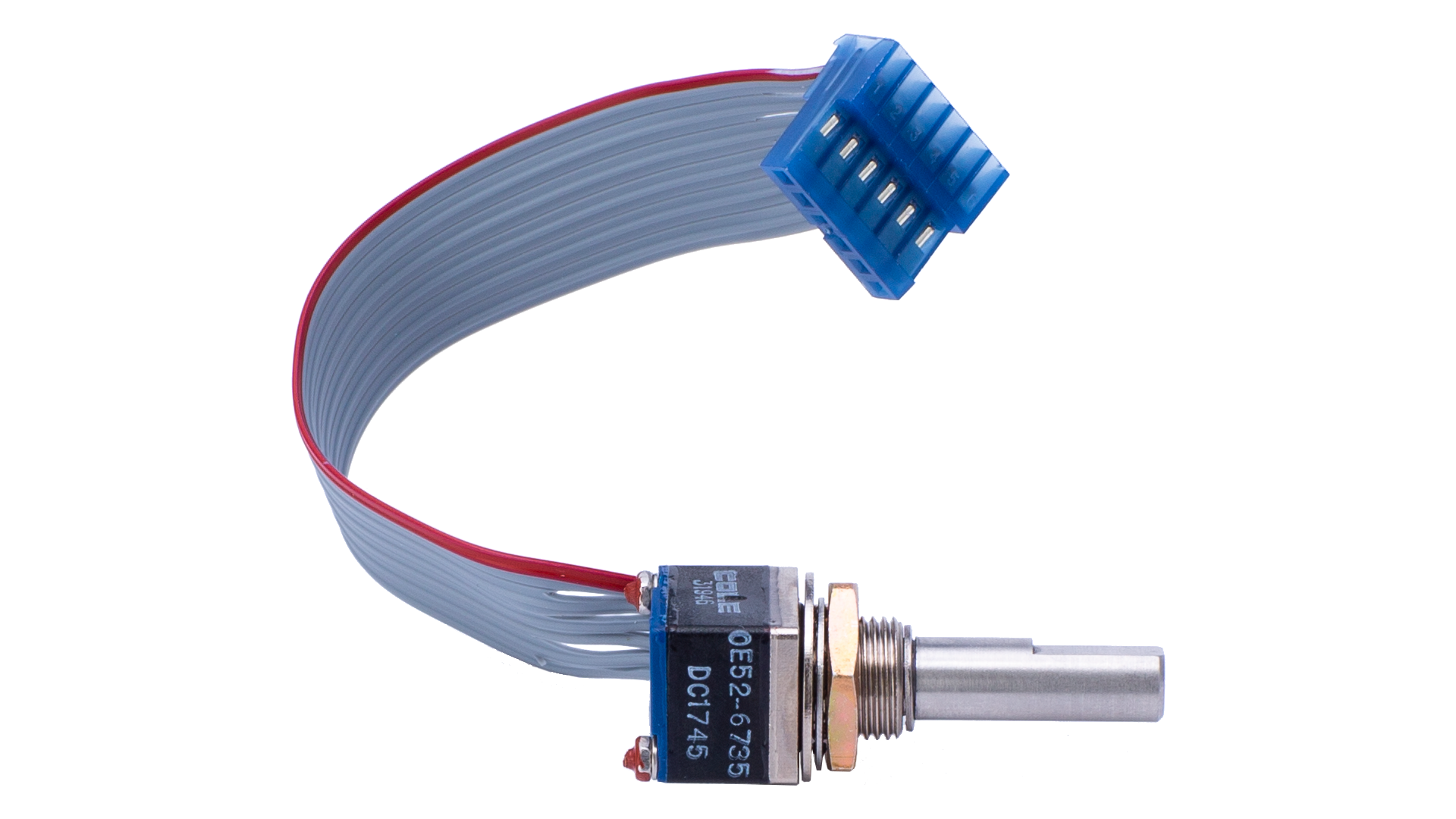
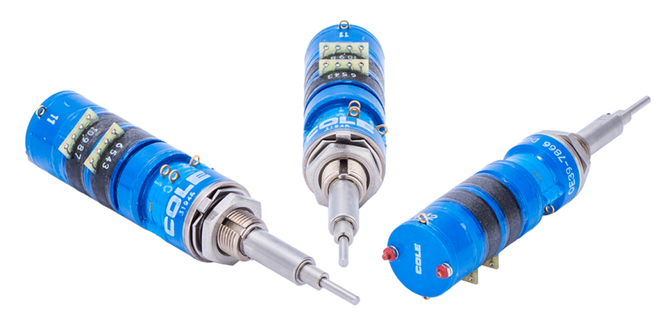
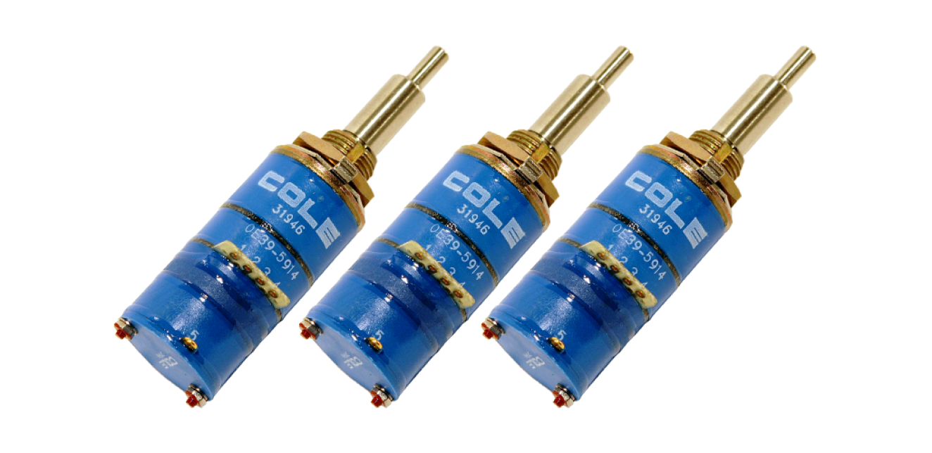
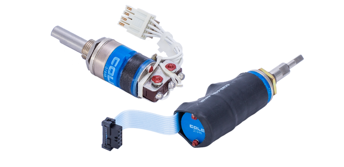
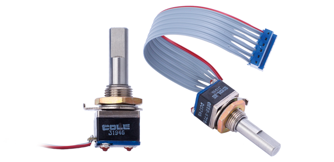
OE-36 SERIES
High Resolution Optical Encoder
OE-36 SERIES
High Resolution Optical Encoder
| Coding |
2 bit quadrature
|
| Operating Voltage |
5.0 ± .5 VDC
|
| Supply Current |
30 mA max.
@ 5 VDC |
| Logic Low Maximum |
0.5 V
|
| Logic High Minimum |
2.5 V
|
| Logic Rise/Fall Time |
<30ms @ 16.6 rpm
|
| Switching Life |
100,000 cycles (1,000,000 available)
|
| Weight |
21 grams
|
| Contact Surfaces | Gold Plated |
| Vibration Tested | YES |
| High Impact Shock Tested | YES |
| Moisture Resistant | YES |
| Salt Spray Resistant | YES |
| Explosion Proof | YES |
| Immersion Tested | YES |
| RFI/EMI Tested | YES |
| Push Button | Available |
| Concentric Shaft | Available |
| Shaft Seal | Available |
| Panel Seal | Available |
OE-36 SERIES
High Resolution Optical Encoder
Information Packet Includes:
- Description
- Product Photos
- Engineering Drawings
- Ordering Information
- Technical Data
- Information on all Optical Encoders
- OE-39H & S Series
- OE-39H/S22 Absolute Positioning Encoder
- OE-39 TCT &TCN Tricentric Shafts Encoder
- OE-39C Concentric Shaft Encoder
- OE-36 High Resolution Series
Cole Instrument Corp. has emerged as a highly competitive manufacturer of Optical Encoders to meet the market's demand for advanced switching technology. This advanced optical technology uses no mechanical contacts, reducing noise and eliminating contact bounce. Optical Encoders are more reliable and longer lasting than conventional rotary switches.
All of our rotary encoders use a quadrature output that is the same as a 2-bit repeating gray code. Quadrature 2-bit code is a relative or incremental code form wherein the direction and magnitude of the optical encoder can be determined, but absolute positioning cannot. In most applications this is not a problem.
In a quadrature rotary optical encoder two detectors are used to provide output “A” and “B”. The code rotor either blocks the infrared light or allows it to pass to the detectors. As the shaft turns the rotor, the output changes state to indicate position. The resulting output is two square waves that are 90° out of phase.
External pull-up resistors from each output to the power source are needed when interfacing with an open collector output to provide the output with the high state voltage when the photo transistor is “off”. Base current is supplied in a photo transistor when light strikes the detector effectively grounding the output. This “on” or “off” digital arrangement allows the open collector to interface with commonly used integrated circuit technologies such as TTL, TTL LS, CMOS and HCMOS.
QUICK LINKS
The Innovative Switch Company
P.O. Box 25063
Santa Ana, CA 92799-5063
ISO 9001:2015
AS9100:2016 Rev. D
Certified
Email: This email address is being protected from spambots. You need JavaScript enabled to view it.
Tel: +714-556-3100


